The Build – Part 4
If Part 4 of the LM-1 build, we assemble and attach the front end. It’s a simple, double a-arm setup that features a pillow-ball upper arm for quick and easy camber adjustments.
Build Notes:
 Threadlock will be needed in a few of these steps, so have some ready!
 Pre-compress the springs prior to installation. This gives them a quick ‘set’.
 The LM-1 have 2 options for the front axle; inline and trailing (you can read about both here: Inline/Trailing Axle. For this build, I’m using the trailing per the instructions.
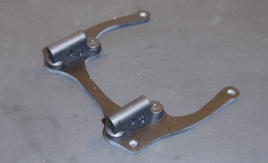
We start off by attaching the caster blocks to the lower arm brace. The kit comes with multiple blocks, but we are starting out with the 10 degree per the manual. Note the orientation of the blocks.
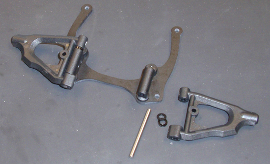
The next step is attaching the upper arms to the caster blocks. To assemble, slide the pin through the upper arm and caster block. Before pushing all the way through, insert 2 1mm spacers on each side as shown. Once you’ve pushed it through all the way, secure with the two 2x5mm socket screws (not shown simply because I forgot to do it).
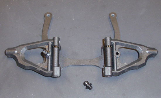
Insert a 3mm ballstud into each upper arm. These are for a front damper that will be installed at a later time.
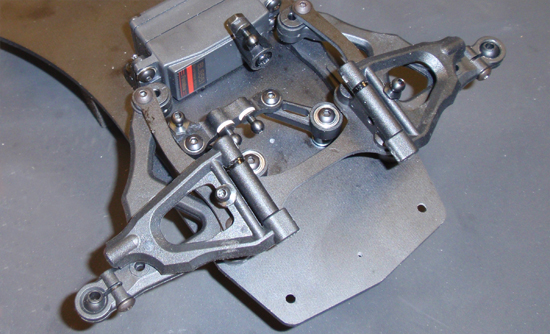
Drop the upper arm assembly into position and secure with the 4 3x6mm button head screws. Do not overtighten.
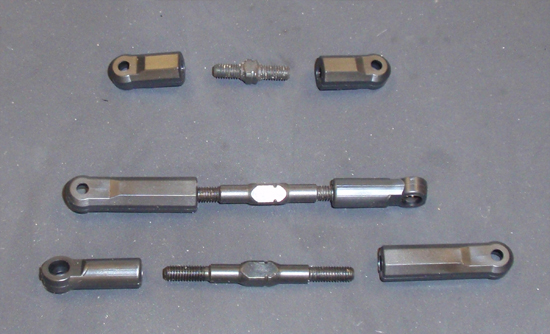
Build 3 turnbuckles; 2 steering and one drag link. The lengths given will be a good start.
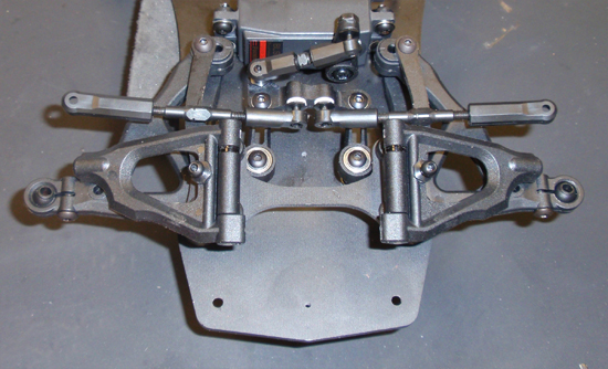
Pop the steering links on as well as the drag link. Note the orientation of the two steering links; the ‘line’ on the adjustment square (on the turnbuckles) should both be pointing the same direction.
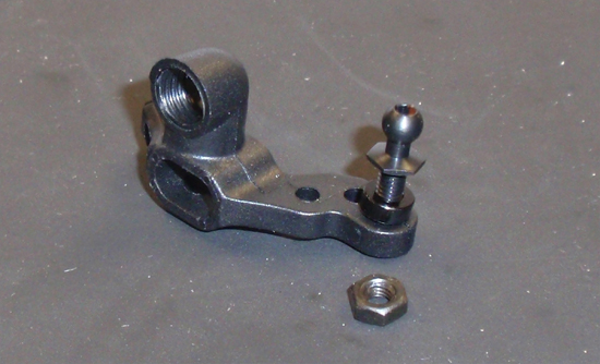
Attach the ballstud to the steering block. Don’t forget to use a 2mm spacer on both sides. You might also want to put a drop of threadlock here.
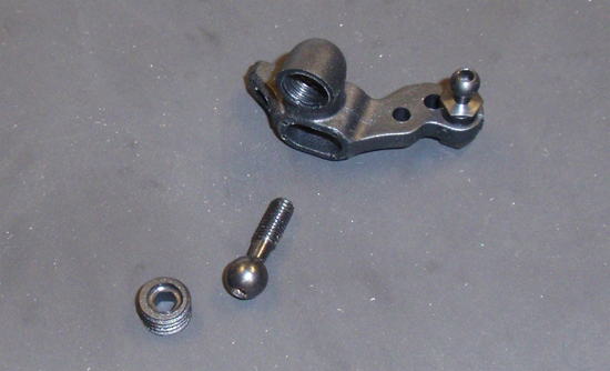
Slide the steering pivot ball into the steering block and CAREFULLY thread the plastic stopper screw into place. This screw is extremely easy to crossthread to take your time here. Also slide the axle into place. We’re setting it up as a trailing axle per the instructions.
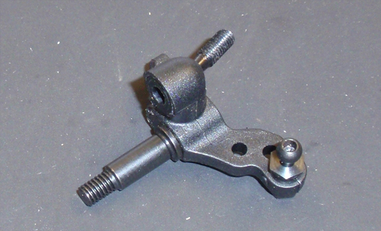
As you can see from this pic, the plastic stopper screw is flush with the steering block, not all crooked and crossthreaded. The steering pivot ball should also have extremely free movement.
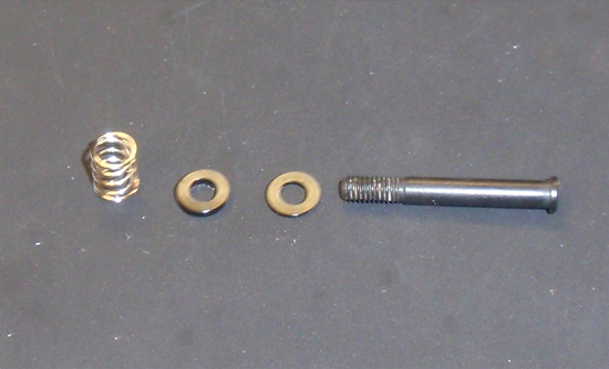
Slide a .5mm and a 1mm shim onto the kingpin, followed by the suspension spring.
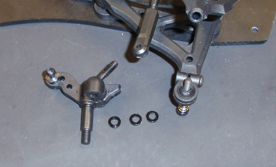
Press the kingpin though the bottom of the front arm, up through the 3 1mm spacers and into the steering block. Thread it in slowly. I initially used the 3mm spacing per the instructions but ended up at about 3.5mm.
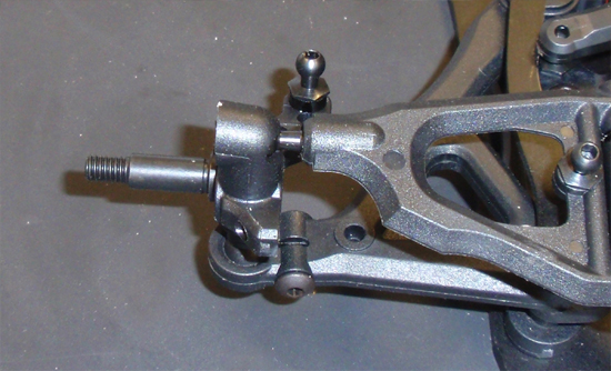
Thread the steering pivot ball into the upper arm as shown. There are no settings for from camber at this point, but I have mine set at about 3.25mm (of the steering pivot ball shaft showing). This will probably be a good start.
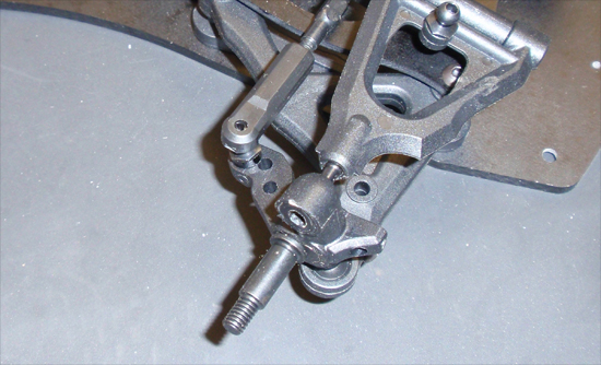
Finally, pop the steering links onto the steering blocks.
 Part 5 – Assembling the rear suspension.
 RC Driver The Best In RC Car & Truck News, Reviews & Video


