The Build – Part 1
We start off the RC10 Classic build with the front suspension. If you’re a long time RC’er (or someone that just happened to have an original RC10 at one time), you’ll be happy to see all of the vintage-style parts in this kit. Let’s get started.
Build Notes:
 FIRST AND FOREMOST!!!! Do NOT throw away any of the tools AE has supplied. I’ll get to that more later, but if you decide not to use them, put them aside and, again, DO NOT THROW THEM AWAY!
 You’ll want to get your hands on a large-tip Phillips screwdriver for parts of this assembly. AE has included the old-skool aluminum Phillips screws and you don’t want to be stripping them out.
 Because this kit is from the way-back time-machine, the bags and their contents don’t coincide 100% with the manual. You may need to open bags further down the line to get the screws you need for an earlier step.
 Threadlock is also required during this assembly so have that ready as well.
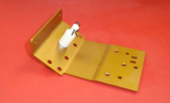
The first step is to attach the front body mount to the front nose plate. Using one of the 8-32 (yellow) aluminum screws, feed it through the front nose plate, through a pair of #8 washers and into the front body mount. To make tightening easier, I installed a body clip to give the body mount more meat to hold on to.
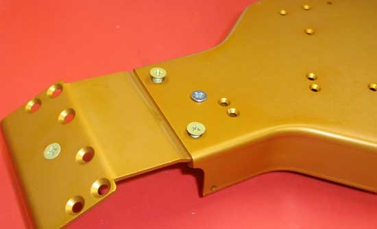
Attach the front nose plate to the chassis using two more 8-32 (yellow) aluminum screws and the short 8/32 screw (silver). Feed the yellow screws in first (but do not tighten) followed by the silver one. A drop of threadlock on the silver screw will keep it in place. After you’ve snugged the silver screw down, snug the yellow ones down.
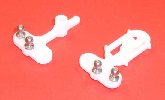
Assemble the steering rack arms as shown. The plastic on these is very similar to the original plastic from years ago, so be careful when tightening down the ball ends. SNUG them down…do not overtighten.
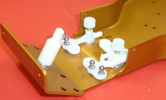
Slide a #8 washer over both yellow screws in the chassis followed by the assembled steering rack arms. Note which arm goes on which side. Slide the servo saver arm onto the LEFT side servo arm as shown and secure both steering rack arms with a 8-32 white nut. Tighten down until snug, then back off about 1/2 turn. You’ll want the steering rack arms to move freely but with as little slip as possible. Adjust the white nuts until you achieve this.
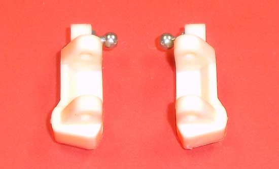
Install a ball end into both caster blocks. Note the orientation of the caster block.

Assemble the steering blocks as shown. You’ll want to make a left and right side. A drop of threadlock will keep the nut attached to the ball end.
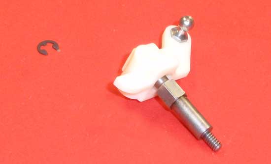
Align the hex on the axle with the hex on the steering block and slide it into place. It may take a little pressure to make it seat all the way into the steering block. Secure with an e-clip.
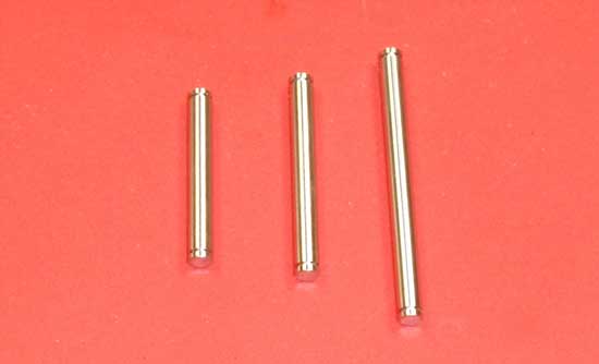
There are three different sizes of hinge pins included in this step. The one of the far left is the kingpin, the one in the middle is the outer hinge pin and the one on the right is the inner hingepin. Grab the one on the left…
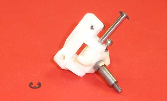
…attach an e-clip to one end and slide it through the caster block and steering block as shown. Note the orientation of the parts. Secure the kinpin on the bottom with another e-clip. Make both sides.
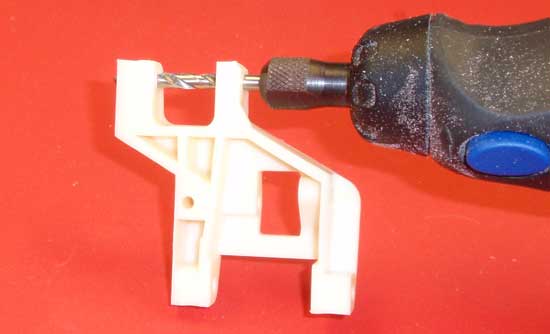
The suspension arms will require a bit of ‘massaging’ to make them move freely after assembled, so this is a good time to do it. Take your hinge pins and slide them through the arms…they should take quite a bit of pressure to push through and the arm will most likely not ‘swing’ on it. We’ll need to remedy that before we move on. Take a 1/8″ drill bit, attach it to your dremel or drill and, on a slow speed, ream out the inner and outer holes of your suspension arms. Test the hinge pin again. If the arms swings freely, you’re good to go. If not, repeat the reaming process until it does. Do this to both the inside and outside hinge pin holes on both arms.
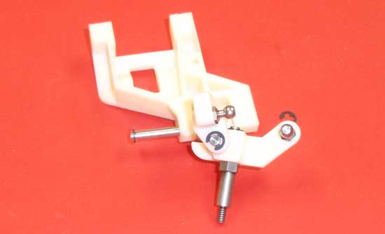
Using the ‘middle’ hinge pin (as described earlier), snap an e-clip to one end and attach the caster block/steering block assembly to the front suspension arm. Note the orientation. Secure with another e-clip on the other end of the hinge pin. Build both sides.
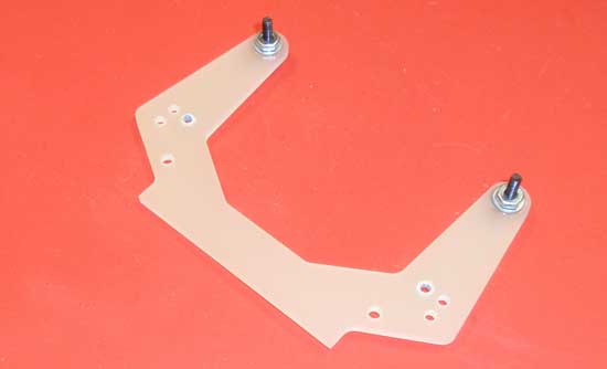
The next step is the shock tower. As you can see, old-skool shock towers were flat so there isn’t a front or back side…just a tower. Start by attaching the shock mount screws to the single hole in the top. The shock mount screws will be in a later bag so you’ll have to find them. Don’t forget the #4 washer and the drop of threadlock to keep the 4-40 nuts in place.
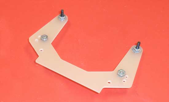
Slide the ballstuds into place and secure with a 4-40 nut. A drop of threadlock here is also required.
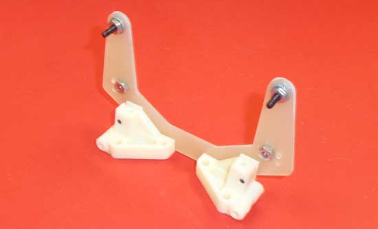
Attach the shock tower assembly to the left and right arm mounts as shown. Note the orientation of the arm mounts. When you’re done, press the assembly on a flat surface (as shown) and rotate the arm mounts until they are flat against the ground.
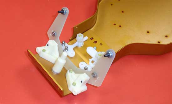
Now attach the shock tower/arm mount assembly to the chassis using 6 of the 8-32 (yellow) screws. Slowly tighten each one to make sure you don’t tweak the final setting point.
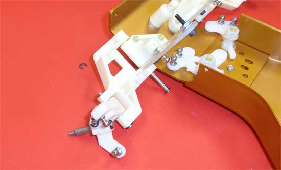
Snap an e-clip to one end of the longest e-clip and attach the left and right suspension arm assembly to the arm mounts. Secure with a final e-clip. I found that sliding the hinge pin up from the bottom (as shown) made snapping the 2nd e-clip on much easier.
 Stay tuned for part 2 – Assembling the transmission.
 RC Driver The Best In RC Car & Truck News, Reviews & Video


